


RECTIFIER CIRCUIT
Why do we need a rectifier Circuit?
Whenever DC power is needed that time, we need to convert an AC Power to DC Power and that process is known as Rectification. A simple PN junction diode acts as a rectifier. The forward biassing and reverse biassing conditions of the diode makes the rectification.
Types of Rectifier circuits
There are two main types of rectifier circuits, depending upon their output. They are
- Half-wave Rectifier
- Full-wave Rectifier
A Half-wave rectifier circuit rectifies only positive half cycles of the input supply whereas a Full-wave rectifier circuit rectifies both positive and negative half cycles of the input supply.
Half-wave Rectifier
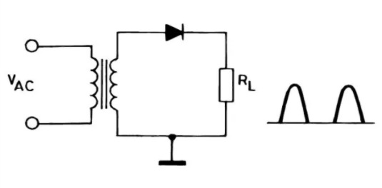
Disadvantages of a half-wave rectifier
- Power is delivered only during the one-half cycle of the input alternating voltage.
- Ripple factor is high, therefore required to give steady dc output.
- They only allow a half cycle through per sine wave, and the other half cycle is wasted. This leads to power loss.
Full-wave rectifier
FWR has two types as follows:
- Centre tapped full wave rectifier
- Bridge full-wave Rectifier
1) Centre tapped full wave rectifier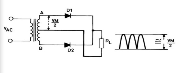
Advantages of a center-tapped full-wave rectifier:
- The ripple factor is much less than that of a half-wave rectifier.
- DC load current values are twice those of a half-wave rectifier.
- The rectification efficiency of the full-wave rectifier is double that of a half-wave rectifier.
Disadvantages of center-tapped full-wave rectifier
- Location of center-tapping is difficult.
- The dc output voltage is small.
- The PIV of the diodes should be high.
2) Full-wave bridge rectifier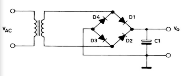
Advantages of bridge rectifier:
- The need for the center-tapped transformer is eliminated.
- It can be used in application floating output terminals; no output terminal is grounded. The transformer utilization factor, in the case of the bridge rectifier, is higher than that of a center tap rectifier.
Disadvantages of Bridge Rectifiers over center tap rectifiers.
- It requires four diodes for operation, thus, circuit components requirements in the case of the bridge rectifier are more than that of center tap rectifiers.
- The voltage drop across diodes increases four times that of a center tap full-wave rectifier.
Types of Components and Its Symbol used in circuit

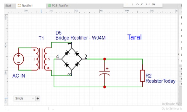
Schematic of bridge rectifier
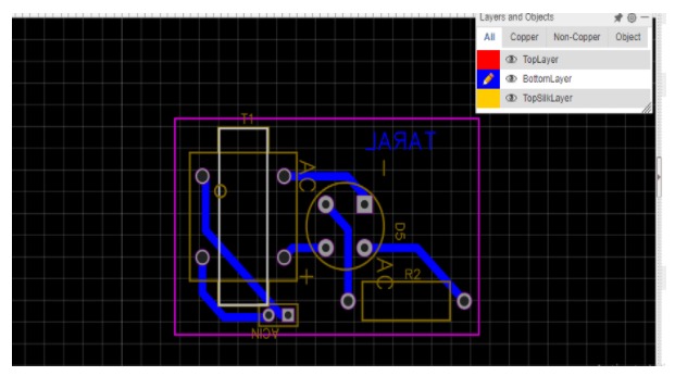
PCB Layout of bridge rectifier
Track Width – 1.00 mm
Bill of material
- During the PCB assembly process, a BOM provides information about the components under a single roof such as their quantity, reference designators, footprints, etc.
- Designers will save lots of time and effort during PCB design by preparing a bill of materials with all the updated parts list.
- Every line of the bill of materials (BOM) includes the product code, part name, part number, part revision, description, quantity, unit of measure, size, length, weight, and specifications or features of the product.
- Go to fabrication bar in Easyeda online tool
- Download BOM
Gerber File
- Each artwork layer, copper circuitry, power, or ground must have a corresponding Gerber file to create the required pattern.
- The outermost layers, referenced as “top” and “bottom,” component and solder or by layer count will also have a conforming layer for solder mask and silkscreen to be applied.
Summary
In this second blog, we have created a schematic of bridge rectifier and pcb layout also and learnt about bill of material and Gerber file. Apart from that we have seen that type of rectifier and understood which one is suitable for industry.
Reference
- https://www.powerelectronicsnews.com/power-supply-design-notes-rectifier-circuits/
- https://www.tutorialspoint.com/electronic_circuits/electronic_circuits_full_wave_rectifier.htm
- https://www.allaboutcircuits.com/textbook/semiconductors/chpt-3/rectifier-circuits/