Communication Protocol\’s in Embedded:
Table of Contents
Communication Protocols in Embedded System
Serial communication
In serial communication, we have only one line for transmitting and receiving data which is why it is half-duplex. It is best for high frequencies as it uses only a single bus or channel for communication, but it can be a bit slower than parallel as it sends only a single bit per clock pulse also because of the single wire here we have fewer chances of cross-talks. It can detect the error as well.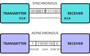
When transferring a bit quick change in voltage are required like for 5v OS, 0 bit communicated as a short pulse is 0v, and 1 bit communicated by a short pulse of 5v. In serial communication, the first bit is the most significant bit and the last one is the least significant bit.
Parallel Communication
In parallel communication, we have a number of lines or buses equal to the number of bits we are transferring. We call it full duplex as the line for transmitting and receiving bits is different. It is faster for small frequencies as all bits are sent at once but as we have to use multiple wires it is costlier also here, we have lots of chances of cross-talks.
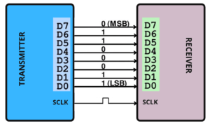
As in serial, here also we have the first bit is the most significant bit and the last one is the least significant bit.
How do they convert?
The protocols we have read above communicate in serial form, but they get the data from their peripheral device in parallel form. How do bits get converted into serial form to parallel form? Suppose we have 4 bits, to convert them from parallel to serial we need a Parallel to Serial converter, In the same way, if we want to convert parallel from series, we need a serial to parallel converter. Here comes the D Flip-Flop which is specially designed for such conversions.
What is Flip-Flop?
A basic memory element or basic digital memory circuit is known as Flip-Flop. It is some medium in which one bit of information (1 or 0) can be stored or retained until it\’s necessary.
- As one flip-flop can store one bit of information. To store multiple bits, we need multiple flip-flops.
- The group of flip-flops, which are used to store the binary data is known as register.
Flip flop circuits are classified into four types based on their use:
- D-Flip Flop
- T- Flip Flop
- SR- Flip Flop
- JK- Flip Flop.
Here for conversion between Serial and parallel bits of data D-Flip Flop is used.
Now, what is D Flip-Flop?
D flip-flop is also known as Data or Delay Flip-Flop. It has a single D input and a clock input C which is why we call it a D flip-flop. Or for the word delay, it describes what happens to the data at input 0. The data at D input is delayed by one clock pulse before it gets to the output Q.
There are two different ways of conversions:
- Parallel to Serial conversion.
- First, we need Flip-Flops equivalent to the number of bits. Then we will put the multiplexer in between the Flip-Flop.
Multiplexer- It is a combinational circuit that takes input from one of many input lines(parallel) and directs it to a single output line(serial).
It has two inputs:
1) From the previous Flip-Flop
2) From Parallel bit data.
Now we will load the data which will be transferred one by one.Here msb will be transferred first.
- Serial to Parallel conversion.
- First, we need Flip-Flops equivalent to the number of bits. This time we won\’t put the multiplexer in between the Flip-Flop.
- We need to store all the bits at first for this we will pull the clock signal low. Once all bits are loaded, we will pull the clock signal high, and it will shift the LSB to the input of Flip-Flop 1 and output of Flip-Flop 0. Same way all bits gets transferred.
- Now all the bits are stored in these Flip-Flop and as shown above all the Flip-Flop will transfer the bits at once the way it happens in parallel..
Overview about Serial Communication Protocols in MCU
UART Protocol
What is UART Protocol?
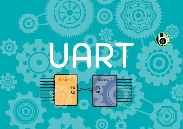
UART stands for Universal Asynchronous Receiver/Transmitter. As we can understand by the name it says it receives and transmits asynchronously. Asynchronously means it doesn\’t use clock pulse to synchronize the transmitter and the receiver.
In UART, the transmitter takes the signals in parallel from a controlling device[ex-CPU] then it sends the bits to a receiver in serial then the receiver converts those bits in parallel again. UART follows one master one slave approach as it uses only 2 wires for communication. It has one transmitter and one receiver.
How does it work?
As I, ve mentioned above it transmits asynchronously hence it uses a start and stops a bit, in it contains main data and a parity bit. The parity bit is only needed if the device needs to check the error.
When the device wants to start the communication, it pulls the transmitting line low which means it sends a 0 bit and receiving device understands that the transmitter wants to send the data. When the transmission line goes lows it stays low for one clock pulse and then it starts sending the data of 8 bits then the 9th one is a parity bit, the last one is stopping bit it stays high for the one clock pulse until the transmitter sends a low bit to start another frame.
To get, in detail understanding on UART Protocol, refer to this blog.
SPI Protocol
What SPI Protocol is?
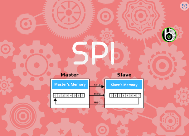
SPI stands for Serial Peripheral Interface. Just like UART it also uses Serial Communication for transmitting and receiving data but instead of asynchronous it uses synchronous communication protocol for transmission.
Synchronous means the transmitter and the receiver must have the same clock signal. It uses a Full duplex communication protocol which means it can send and receive at the same time. SPI follows one Master multiple slave configuration.
This protocol has 4 parts
1. MOSI-Master Out Slave In
Here Master sends data to the slave and the slave receives the data. Master sends data to each device it is connected to via a single wire.
2. MISO-Master In slave out
Here Slave sends the data to the master and the master receives the Data. Master receives the data from each device it is connected to through a single wire.
3. CLK-Clock Signal
It is important for synchronizing the data when the master sends or receives it.
4. CS/SS-Chip select/slave select
We have different wires connected to the chips. Suppose we have 3 chips connected. Then the master would have three wires cs1,cs2,cs3 connected from chip1, chip2,chip3 individually.
To get in detail understanding on SPI Protocol, refer this blog.
I2C Protocol
I2C stands for the inter-integrated circuit. If you have read carefully about SPI and UART you will find I2C got the best features of these two.
It follows multi-master protocol as multiple masters through a single slave or to multiple slaves. It is a half-duplex communication protocol since it has only one line for transferring and receiving data. It is also called Two Wired Interface as it uses two wires for communication.
This protocol has 2 parts
- SDA: For sending bits
- SCL: For synchronizing the data.
How does it work?
In I2C as we have multiple slaves, every slave must have a different address before sending a bit master will address or call the receiver. If we have multiple masters then the master will check the clock signal. If it is high it will send the data or if it is low then it means another master is sending the data at the moment.
To get more in detail understanding of I2C protocol, refer to this blog.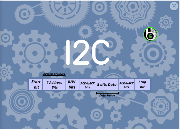
Conclusion Para
- In the end, if you want to use two devices then UART works best and fastest.
- If you have multiple slaves and one master then I would suggest going for SPI
- And if you want to connect one slave with multiple masters then I2C is the fastest as it lowers the wirings as well.
Other blogs to explore
About Microcontrollers
About IoT
SPI Peripheral in S32K144 MCU
So hello guys, welcome back to NXP Semiconductors S32K144 MCU Tutorial series. In the last 2 blogs we had started with S32K144 MCU GPIO Peripheral & UART Peripheral .
UART Peripheral in S32K144 MCU
So hello guys, welcome back to NXP Semiconductors S32K144 MCU Tutorial series. In the last blog we had started with S32K144 MCU GPIO Peripheral. In this blog
Introduction to Atmel studio
I assume if you are here to do projects on Atmel studio using embedded c then you are familiar with Arduino IDE. If not then
Getting Started with S32 Design Studio Part 2
Table of Contents Overview So, hello guys, welcome to Gettobyte website. This blog is part of the Microcontroller coding series on NXP Semiconductors S32K144 MCU.
STM32F103 & ADC: Single Channel Conversion
In the last post, we have gotten to know about the features of ADC Peripheral that we have in STM32 MCU. Now in this blog
Author


