UART Peripheral in STM32F103
Overview
So, welcome to the series of STMicroelectronics, STM32F103 microcontroller coding series, in which we are covering its various peripheral coding.
As covered in the last blog’s we have covered various peripherals of STM32F103 MCU and understand their working, in this blog we’ll be covering one of those special or alternate functions of the GPIO pins i.e. the UART(USART) functionality of these pins. Before discussing UART we’ll be discussing different types of communication.
Other blogs to explore:
Types of Serial Communication

In Serial Communication the 8 bit data is transferred between 2 devices one bit at a time .This usually requires a single wire reducing the need for extra wires but compromising on the speed as the data is sent or received 1 bit at a time.This communication scheme is simple , cost effective and efficient for long distances and high frequencies.It also requires start and stop bits to synchronize the data.
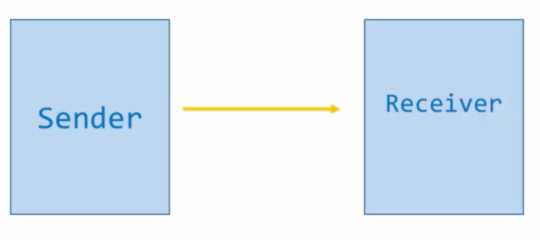
In Parallel communication all the 8 bits are sent simultaneously along 8 input output lines.All the 8 bits are sent in a single cycle hence this data communication scheme is faster . This data transfer scheme is complex and efficient and faster at smaller distances. It needs no synchronizing bits as the data is received in a single clock cycle.
 UART IS A TYPE OF SERIAL DATA COMMUNICATION PROTOCOL
Other Serial Communication Peripherals and protocols


UART Theory
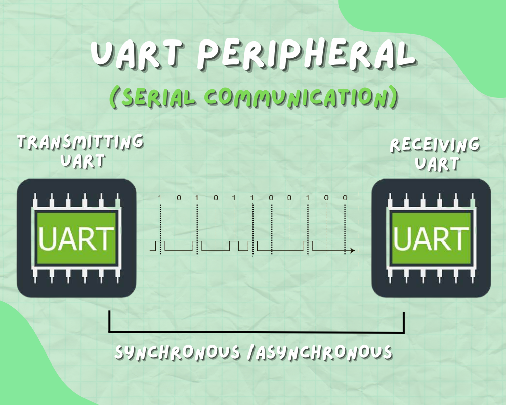
So UART is a type of serial communication protocol in which data is sent serially bit by bit over a single wire both in synchronous and asynchronous mode. In which each frame comprises of a start bit , a stop bit and 8 data bits with an exception of parity bits.
Types of communication in USART (serial) communication: –
- Synchronous – Clock is transmitted with the data.
- Asynchronous – Their is no clock when the data is send, instead data in itself has start and stop bits for indicating when data is started and ended.


Hence the whole module is called USART(Universal Synchronous Asynchronous Receiver Transmitter)
Transmission MODES in USART
DUPLEX- The data can be transmitted and received.
SIMPLEX- The data can only be transmitted or received.

Duplex can be further divided into: –
HALF DUPLEX-In this data can only be transmitted in only one way.

FULL DUPLEX- In this data can be transmitted both ways at a time.

HOW A SINGLE CHARACTER IS TRANSMITTED IN UART PROTOCOL
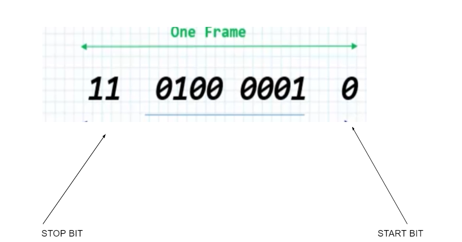
- In asynchronous communication the data is packed between start and stop bits
- The start bit is usually one and the stop can be 1 or 2 bits
- For transmission to begin the value of start bit is turned to ‘0’
- For transmission to end the value of the stop bit is turned to ‘1’ or ‘11’
- And between the start and stop bit, there is 8-10 bits of word length which is actual data, which consists of 0 and 1 values
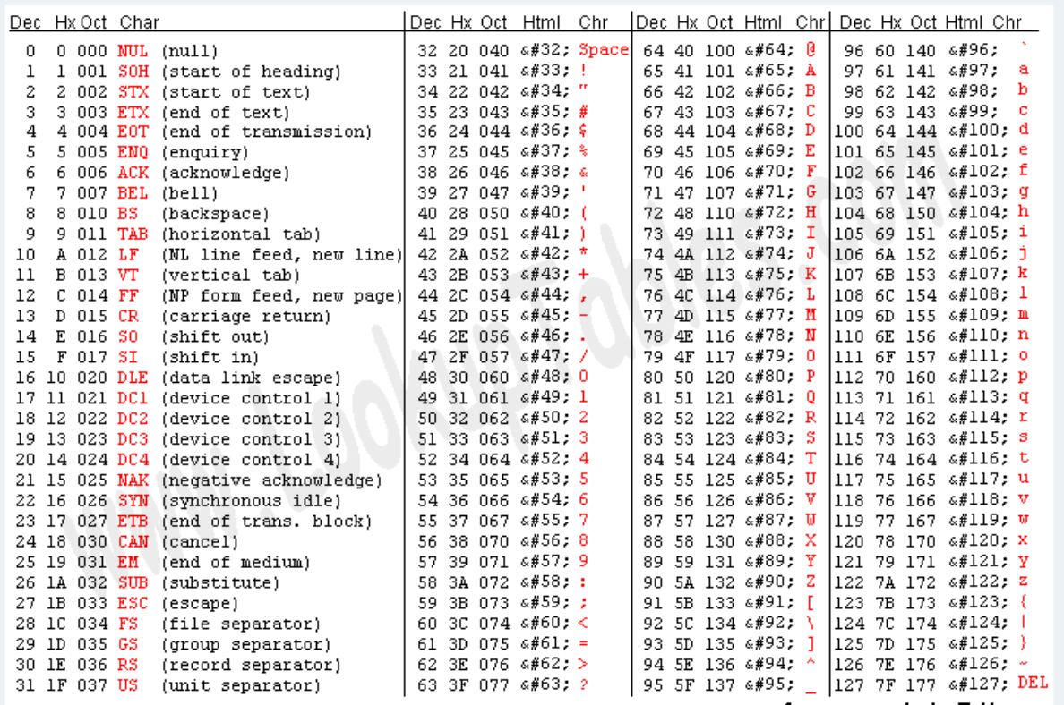
- This actual data is send in binary format, this binary format is mapped to human understable characaters like alphabets, number, signs using the ASCII table.
ASCII table is universal table, in which every English alphabet, mathematical number and different signs have been mapped to binary number in the hex and decimal format. Like in the below table, if u take character A, it is mapped to value of 0x41 which is in binary is: 01000001. That is what is transmitted as bits in word length in UART One Frame.
UART CONFIGURATION PARAMETERS
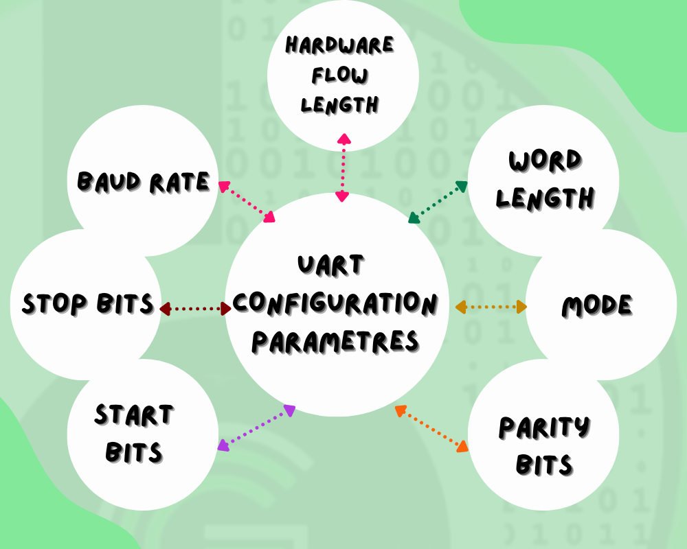
BAUD RATE
Specifies the agree upon clock speed of the communication of the bits between transmitter or receiver.
STOP BITS
Specifies the end of transmission .They maybe 1 bit or 2 bits i.e when the transmission ends the stop bits maybe 1 or 11
START BIT
They state the start of transmission and are 1 bit
PARITY BITS
This indicates the parity mode whether odd or even . This is used to check for errors
MODE
Specifies the mode enable by the specified pin which is TX, RX or TX and RX.
WORD LENGTH
Specifies the no of data bits transmitted or received .The value varies between 8 or 9 bits
HARDWARE FLOW CONTROL
Is a strategy for communication between slow and fast devices without loss of data.This can either be enabled or disabled.
- It is used to send bits or strings of data between devices using single wire communication
- Communication between serial ports of computers and embedded devices such a microcontroller and sensors
- UART can also be used as an inexpensive alternative to USB as it was used in earlier computers for keyboard and mouse
- It is an important tool for debugging and connecting with external hardware like RFID, GPS, GSM, WiFi , BLE modems for performing communication related works.


UART Features in STM32F103
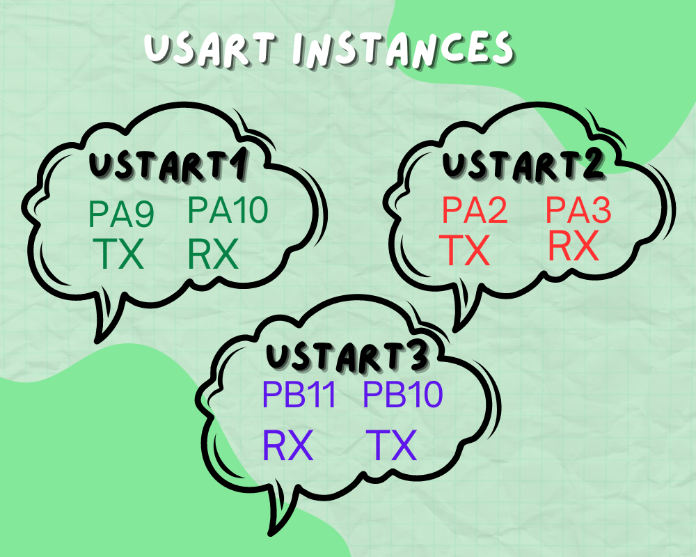
USART INSTANCES in STM32F103
There are 3 usart instances USART1 , USART2 and USART3.
- To configure USART1 the pins the pin PA9 will be TX and pin PA10 will be RX
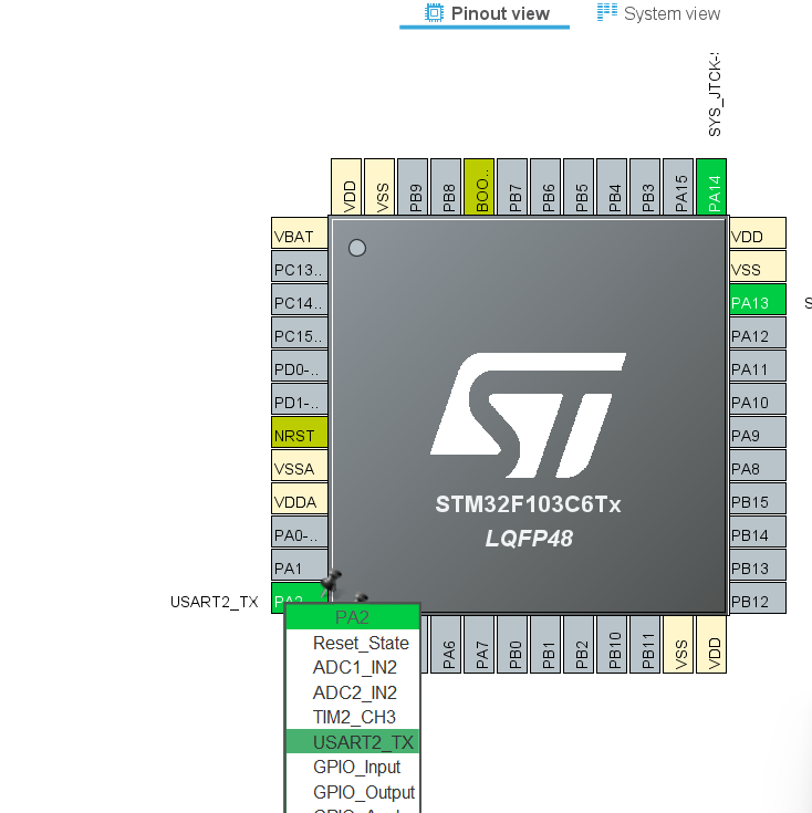
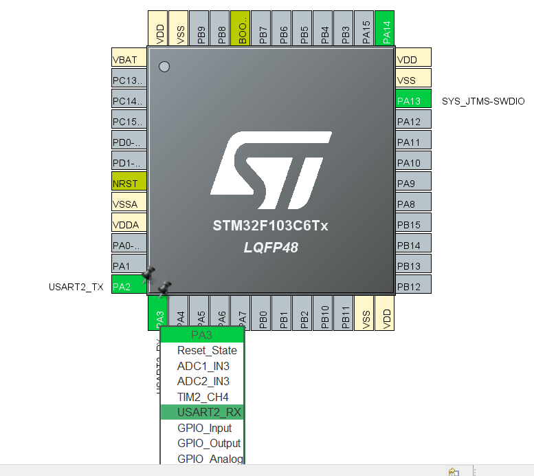
- In case of USART2 the pin PA2 will be TX and PA3 will be RX
- For USART 3 the RX and TX will be PB11 and PB10 respectively.
- The USART supports LIN (local interconnection network), Smartcard Protocol and IrDA (infrared data association) SIR ENDEC specifications, and modem operations (CTS/RTS).
- Smartcard is a single wire half duplex communication protocol.The smartcard mode can be selected by setting the SCEN bit in the USART_CR3 register while LINEN bit in the USART_CR2 register, HDSEL and IREN bits in the USART_CR3 register are kept in clear mode.The CLKEN bit may be set in order to provide a clock to the smartcard.
- The IrDA mode is selected by setting the IREN bit in the USART_CR3 register. In IrDA mode LINEN, STOP and CLKEN bits in the USART_CR2 register, SCEN and HDSEL bits in the USART_CR3 register are cleared.
- The LIN mode is selected by setting the LINEN bit in the USART_CR2 register. The STOP[1:0], CLKEN in the USART_CR2 register SCEN, HDSEL and IREN in the USART_CR3 register are cleared for the selection of LIN mode
USART MODE CONFIGURATIONS TABLE

How to configure the UART peripheral pin in STM32F103?
We would be using STM32 HAL and STM32CubeIDE for using the UART peripheral in STM32F103 in this blog tutorial series.
Configurations in STM32CubeIDE for STM32F103
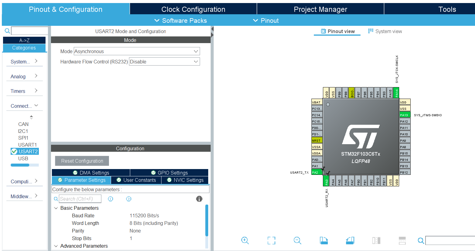
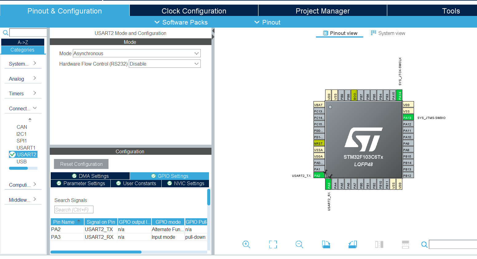
STM32 HAL Peripheral Data Handling API types
- Non Interrupt Based(Polling type)
- Interrupt Based
- DMA Based (Uses DMA and Interrupts)
In polling method the cpu tasks is blocked until a certain amount of UART bytes are received after that CPU continues its normal operation . The demerit being that the microcontroller has to be turned on for whole operation.
For eg –HAL_UART_Receive (&huart1, UART1_rxBuffer, 20, 4000);
This means that until the 20 bytes are received by the CPU it will stop its normal operation by 4s
In interrupt based the completion of the process is indicated by interrupt.The CPU fires an interrupt signal when the data is received notifying the completion of process.The CPU continues its normal operation when receiving the data . When the interrupt is received it freezes the main context and switches to ISR handler to save the receive data in to a buffer
For eg –HAL_UART_Receive_IT(&huart1, UART1_rxBuffer, 12);
The non blocking mode even though an efficient method in receiving small bytes of data becomes inefficient in large data cases as huge no of interrupts wastes CPU time
The DMA based approach is the most efficient way to receive the data . In DMA mode the data is received from the peripheral to the memory location (pre-programmed) without CPU intervention. The main application code is setup to execute the operation the DMA notifies the CPU about completion of data receiving in the data buffer of the pre-programmed location.
For eg- HAL_UART_Receive_DMA (&huart1, UART1_rxBuffer, 12);
The DMA also assigns the channel priorities, data width and even amount of data to be transferred.
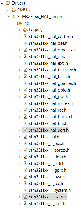
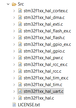
STM32 HAL SDK Files for UART
- stm32f1xx_hal.c
- Stm32f1xx_hal_uart.c
- Stm32f1xx_hal_uart.h
- Stm32f1xx_ll_usart.h
- Stm32f1xx_hal_msp.c
Stm32f1xx_hal_msp.c consists of void HAL_UART_MspInit which is used to initialize the gpio peripheral and configure hardware resources to act as UART module
Stm32f1xx_hal_uart.h consists of UART init structure definition which consists of various parameters such as parity bits , stop bits,baud rate, word length, mode, Hwflowctl etc . It also consists of various macro definition , enum and error types.
Stm32f1xx_hal_uart.c consists of Uart macros , configuration and initialization of hardware resources configuring functions
DEMO EXERCISE
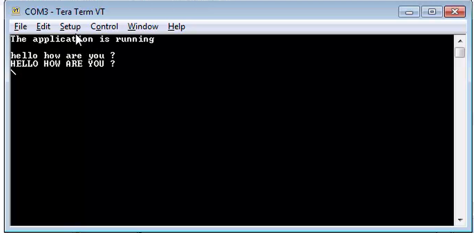
CONVERTING THE RECEIVED DATA INTO ALL CAPITAL LETTERS
					  uint8_t conv_to_caps(uint8_t data);
  uint8_t receiveddat;
  uint8_t datbuffer[100];
  uint32_t count=0;
  char *data="The application is running \r\n";
  uint32_t lengdat = strlen(data);
       HAL_UART_Transmit(&huart2,(uint8_t*)data,lengdat,HAL_MAX_DELAY);


  /* Infinite loop */
  /* USER CODE BEGIN WHILE */
  while (1)
  {
    /* USER CODE END WHILE */
	  HAL_UART_Receive (&huart2, &receiveddat, 1, HAL_MAX_DELAY);/*STEP 2*/
	    if(receiveddat == '\r'){
	    	break;
	    }
	    else{
	    	datbuffer[count++]= conv_to_caps(receiveddat);/*STEP 4*/
	    }
    /* USER CODE BEGIN 3 */

  /* USER CODE END 3 */
}
  datbuffer[count++]='\r';
  HAL_UART_Transmit(&huart2,datbuffer,count,HAL_MAX_DELAY);/*STEP 5*/
static void MX_USART2_UART_Init(void)
{

  /* USER CODE BEGIN USART2_Init 0 */

  /* USER CODE END USART2_Init 0 */

  /* USER CODE BEGIN USART2_Init 1 */

  /* USER CODE END USART2_Init 1 */
  huart2.Instance = USART2; /*STEP 1*/
  huart2.Init.BaudRate = 115200;
  huart2.Init.WordLength = UART_WORDLENGTH_8B;
  huart2.Init.StopBits = UART_STOPBITS_1;
  huart2.Init.Parity = UART_PARITY_NONE;
  huart2.Init.Mode = UART_MODE_TX_RX;
  huart2.Init.HwFlowCtl = UART_HWCONTROL_NONE;
  huart2.Init.OverSampling = UART_OVERSAMPLING_16;
  if (HAL_UART_Init(&huart2) != HAL_OK)
  {
    Error_Handler();
  }
  /* USER CODE BEGIN USART2_Init 2 */

  /* USER CODE END USART2_Init 2 */

}

/**
  * @brief GPIO Initialization Function
  * @param None
  * @retval None
  */
static void MX_GPIO_Init(void)
{

  /* GPIO Ports Clock Enable */
  __HAL_RCC_GPIOA_CLK_ENABLE();

}

/* USER CODE BEGIN 4 */

/* USER CODE END 4 */

/**
  * @brief  This function is executed in case of error occurrence.
  * @retval None
  */
uint8_t conv_to_caps(uint8_t data){    /*STEP 3*/
	if(data >='a' && data<= 'z'){
		data = data - ('a'-'A');

	}
	return data;
}
NOTE- The above code could be implemented using printf functionality with using IO_Putchar function
PRINT SINGLE CHARACTER
					uint8_t test[1]="H";

/**
  * @brief  The application entry point.
  * @retval int
  */
int main(void)
{
  /* USER CODE BEGIN 1 */

  /* USER CODE END 1 */

  /* MCU Configuration--------------------------------------------------------*/

  /* Reset of all peripherals, Initializes the Flash interface and the Systick. */
  HAL_Init();

  /* USER CODE BEGIN Init */

  /* USER CODE END Init */

  /* Configure the system clock */
  SystemClock_Config();

  /* USER CODE BEGIN SysInit */

  /* USER CODE END SysInit */

  /* Initialize all configured peripherals */
  MX_GPIO_Init();
  MX_USART1_UART_Init();
  /* USER CODE BEGIN 2 */
  HAL_UART_Transmit(&huart1, test, sizeof(test), 25);

}
PRINT STRING
					#include
/* Private includes ----------------------------------------------------------*/
/* USER CODE BEGIN Includes */

/* USER CODE END Includes */

/* Private typedef -----------------------------------------------------------*/
/* USER CODE BEGIN PTD */

/* USER CODE END PTD */

/* Private define ------------------------------------------------------------*/
/* USER CODE BEGIN PD */
/* USER CODE END PD */

/* Private macro -------------------------------------------------------------*/
/* USER CODE BEGIN PM */

/* USER CODE END PM */

/* Private variables ---------------------------------------------------------*/
UART_HandleTypeDef huart1;

/* USER CODE BEGIN PV */
void uprintf(char *str){
	HAL_UART_Transmit(&huart1, (uint8_t *)str, strlen(str), 25);
}
/* USER CODE END PV */

/* Private function prototypes -----------------------------------------------*/
void SystemClock_Config(void);
static void MX_GPIO_Init(void);
static void MX_USART1_UART_Init(void);
/* USER CODE BEGIN PFP */

/* USER CODE END PFP */
while (1)
  {
    /* USER CODE END WHILE */
     uprintf("PRATYUSH KAUSHIK\n");
     HAL_Delay(1000);
    /* USER CODE BEGIN 3 */
  }
  /* USER CODE END 3 */
}
INT X++
					#include "main.h"
#include
#include
/* Private includes ----------------------------------------------------------*/\
char buffer[32]={0};
uint8_t count=0;
/* USER CODE BEGIN Includes */

/* USER CODE END Includes */

/* Private typedef -----------------------------------------------------------*/
/* USER CODE BEGIN PTD */

/* USER CODE END PTD */

/* Private define ------------------------------------------------------------*/
/* USER CODE BEGIN PD */
/* USER CODE END PD */

/* Private macro -------------------------------------------------------------*/
/* USER CODE BEGIN PM */

/* USER CODE END PM */

/* Private variables ---------------------------------------------------------*/
UART_HandleTypeDef huart1;

/* USER CODE BEGIN PV */
void uprintf(char *str){
	HAL_UART_Transmit(&huart1, (uint8_t *)str, strlen(str), 25);
}
/* USER CODE END PV */

/* Private function prototypes -----------------------------------------------*/
void SystemClock_Config(void);
static void MX_GPIO_Init(void);
static void MX_USART1_UART_Init(void);
/* USER CODE BEGIN PFP */

/* USER CODE END PFP */

/* Private user code ---------------------------------------------------------*/
/* USER CODE BEGIN 0 */

/* USER CODE END 0 */


/**
  * @brief  The application entry point.
  * @retval int
  */
int main(void)
{
  /* USER CODE BEGIN 1 */

  /* USER CODE END 1 */

  /* MCU Configuration--------------------------------------------------------*/

  /* Reset of all peripherals, Initializes the Flash interface and the Systick. */
  HAL_Init();

  /* USER CODE BEGIN Init */

  /* USER CODE END Init */

  /* Configure the system clock */
  SystemClock_Config();

  /* USER CODE BEGIN SysInit */

  /* USER CODE END SysInit */

  /* Initialize all configured peripherals */
  MX_GPIO_Init();
  MX_USART1_UART_Init();
  /* USER CODE BEGIN 2 */


  /* Infinite loop */
  /* USER CODE BEGIN WHILE */
  while (1)
  {
	 count++;
    /* USER CODE END WHILE */
	 sprintf(buffer, "count :%d\n", count);
	 uprintf(buffer);
	 HAL_Delay(1000);
    /* USER CODE BEGIN 3 */
  }
  /* USER CODE END 3 */
}
PRINT FLOATING TYPE
					#include
#include
/* Private includes ----------------------------------------------------------*/\
char buffer[32]={0};
uint8_t count=0;
float pi=3.14;
/* USER CODE BEGIN Includes */

/* USER CODE END Includes */

/* Private typedef -----------------------------------------------------------*/
/* USER CODE BEGIN PTD */

/* USER CODE END PTD */

/* Private define ------------------------------------------------------------*/
/* USER CODE BEGIN PD */
/* USER CODE END PD */

/* Private macro -------------------------------------------------------------*/
/* USER CODE BEGIN PM */

/* USER CODE END PM */

/* Private variables ---------------------------------------------------------*/
UART_HandleTypeDef huart1;

/* USER CODE BEGIN PV */
void uprintf(char *str){
	HAL_UART_Transmit(&huart1, (uint8_t *)str, strlen(str), 25);
}
/* USER CODE END PV */

/* Private function prototypes -----------------------------------------------*/
void SystemClock_Config(void);
static void MX_GPIO_Init(void);
static void MX_USART1_UART_Init(void);
/* USER CODE BEGIN PFP */

/* USER CODE END PFP */

/* Private user code ---------------------------------------------------------*/
/* USER CODE BEGIN 0 */

/* USER CODE END 0 */


/**
  * @brief  The application entry point.
  * @retval int
  */
int main(void)
{
  /* USER CODE BEGIN 1 */

  /* USER CODE END 1 */

  /* MCU Configuration--------------------------------------------------------*/

  /* Reset of all peripherals, Initializes the Flash interface and the Systick. */
  HAL_Init();

  /* USER CODE BEGIN Init */

  /* USER CODE END Init */

  /* Configure the system clock */
  SystemClock_Config();

  /* USER CODE BEGIN SysInit */

  /* USER CODE END SysInit */

  /* Initialize all configured peripherals */
  MX_GPIO_Init();
  MX_USART1_UART_Init();
  /* USER CODE BEGIN 2 */


  /* Infinite loop */
  /* USER CODE BEGIN WHILE */
  while (1)
  {

    /* USER CODE END WHILE */
	 sprintf(buffer, "Float Val : %f\n", pi);
	 uprintf(buffer);
	 HAL_Delay(1000);
    /* USER CODE BEGIN 3 */
  }
  /* USER CODE END 3 */
}
HAL APIs and other function involved
- HAL_StatusTypeDef HAL_UART_Init (UART_HandleTypeDef * huart)
- HAL_StatusTypeDef HAL_UART_Transmit (UART_HandleTypeDef * huart, uint8_t * pData, uint16_t Size, uint32_t Timeout)
- HAL_StatusTypeDef HAL_UART_Receive (UART_HandleTypeDef * huart, uint8_t * pData, uint16_t Size, uint32_t Timeout )
- static void MX_USART2_UART_Init(void)
- void HAL_UART_MspInit(UART_HandleTypeDef* huart)
FUNCTION NAME
HAL_StatusTypeDef HAL_UART_Init (UART_HandleTypeDef * huart)
FUNCTION DESCRIPTION
Initializes the UART port according to the given parameters in UART_InitTypeDef and create the associated handle
PARAMETERS
UART_HandleTypeDef * huart – takes in pointer to the structure UART_HandleTypeDef that helps in configuring the port according to parameters specified by the UART module
RETURN TYPE
NONE
FUNCTION NAME
HAL_StatusTypeDef HAL_UART_Transmit (UART_HandleTypeDef * huart, uint8_t * pData, uint16_t Size, uint32_t Timeout) 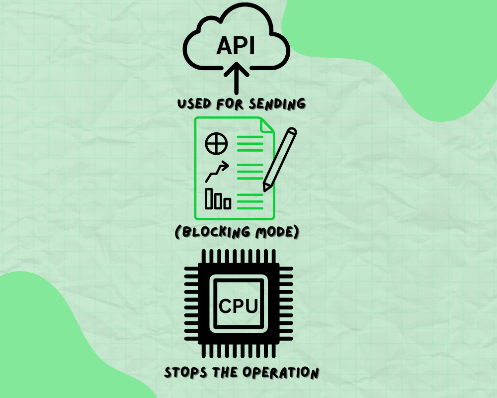
FUNCTION DESCRIPTION
This API is used for sending the data in blocking mode i.e the CPU stops the operation until the data is transferred
PARAMETERS
UART_HandleTypeDef * huart – The pointer to the structure UART_HandleTypeDef that contains the information of configuration of the uart module
uint8_t * pData – The pointer to the data buffer that stores the data
uint16_t Size – The size of the data to be sent(size of array or size of the string)
uint32_t Timeout – The time for which the blocking mode prevails
RETURN TYPE
HAL- STATUS
					USAGE
    char *data="Hello from stm32 \r\n";
  /* Infinite loop */
  /* USER CODE BEGIN WHILE */
  while (1)
  {
    /* USER CODE END WHILE */
       uint32_t lengdat = strlen(data);
       HAL_UART_Transmit(&huart2,(uint8_t*)data,lengdat,HAL_MAX_DELAY);

    /* USER CODE BEGIN 3 */
  }
FUNCTION NAME
HAL_StatusTypeDef HAL_UART_Receive (UART_HandleTypeDef * huart, uint8_t * pData, uint16_t Size, uint32_t Timeout)
FUNCTION DESCRIPTION
Receives the specified amount of data in blocking mode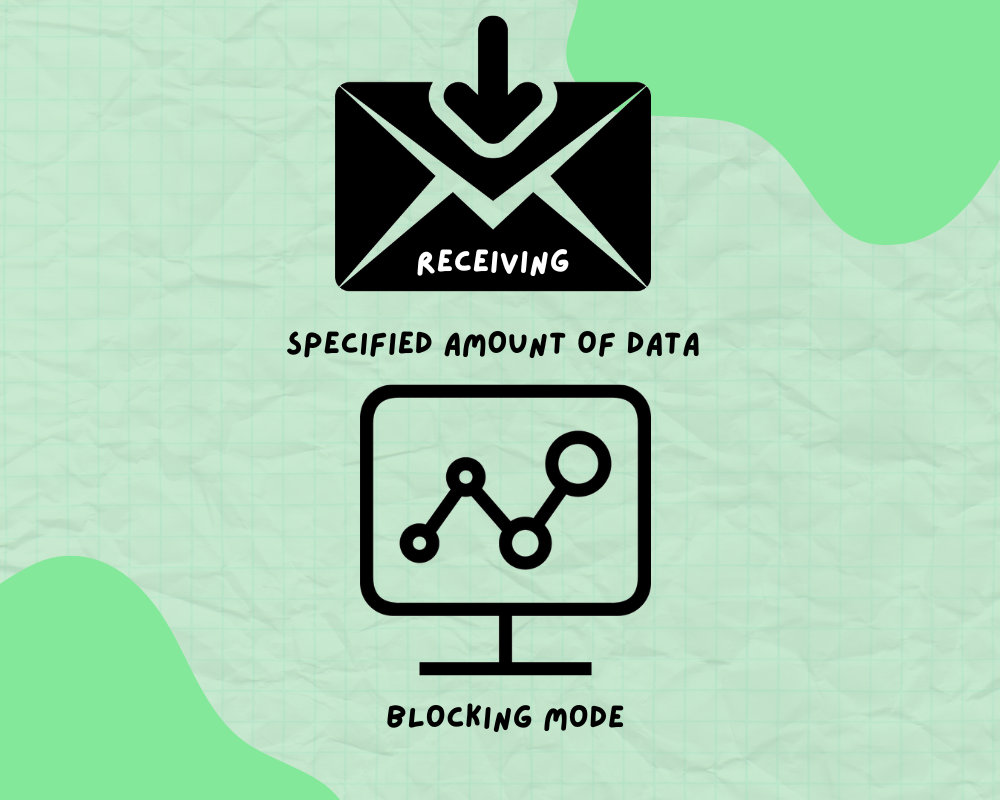
PARAMETERS
UART_HandleTypeDef * huart – The pointer to the structure UART_HandleTypeDef that contains the information of configuration of the uart module
uint8_t * pData – The pointer to the data buffer that stores the data
uint16_t Size – The size of the data to be sent(size of array or size of the string)
uint32_t Timeout – The time for which the blocking mode prevails
RETURN TYPE
HAL- STATUS
					uint8_t receiveddat;
  uint8_t datbuffer[100];
  uint32_t count=0;
  /* Infinite loop */
  /* USER CODE BEGIN WHILE */
  while (1)
  {
    /* USER CODE END WHILE */
       if(receiveddat=='\r’)
    	   break;
       }
              else{
       HAL_UART_Receive (&huart2, &receiveddat, 1, HAL_MAX_DELAY);
	  datbuffer[count++]=receiveddat;
       }


      }
FUNCTION NAME
static void MX_USART2_UART_Init(void)
FUNCTION DESCRIPTION
Initializes the uart module according to parameters such as baudrate, wordlength, stopbits etc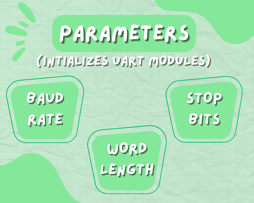
PARAMETERS
NONE
RETURN TYPE
NONE
					static void MX_USART2_UART_Init(void)
{

  /* USER CODE BEGIN USART2_Init 0 */

  /* USER CODE END USART2_Init 0 */

  /* USER CODE BEGIN USART2_Init 1 */

  /* USER CODE END USART2_Init 1 */
  huart2.Instance = USART2;
  huart2.Init.BaudRate = 115200;
  huart2.Init.WordLength = UART_WORDLENGTH_8B;
  huart2.Init.StopBits = UART_STOPBITS_1;
  huart2.Init.Parity = UART_PARITY_NONE;
  huart2.Init.Mode = UART_MODE_TX_RX;
  huart2.Init.HwFlowCtl = UART_HWCONTROL_NONE;
  huart2.Init.OverSampling = UART_OVERSAMPLING_16;
  if (HAL_UART_Init(&huart2) != HAL_OK)
  {
    Error_Handler();
  }
  /* USER CODE BEGIN USART2_Init 2 */

  /* USER CODE END USART2_Init 2 */

}
FUNCTION NAME
void HAL_UART_MspInit(UART_HandleTypeDef* huart)
FUNCTION DESCRIPTION
Initialize the microcontroller support package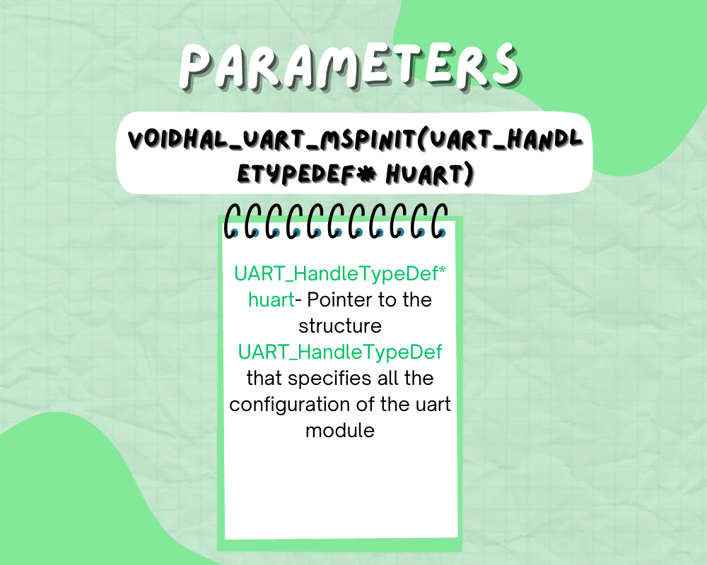
PARAMETERS
UART_HandleTypeDef* huart- Pointer to the structure UART_HandleTypeDef that specifies all the configuration of the uart module
					void HAL_UART_MspInit(UART_HandleTypeDef* huart)
{
  GPIO_InitTypeDef GPIO_InitStruct = {0};
  if(huart->Instance==USART2)
  {
  /* USER CODE BEGIN USART2_MspInit 0 */

  /* USER CODE END USART2_MspInit 0 */
    /* Peripheral clock enable */
    __HAL_RCC_USART2_CLK_ENABLE();

    __HAL_RCC_GPIOA_CLK_ENABLE();
    /**USART2 GPIO Configuration
    PA2     ------> USART2_TX
    PA3     ------> USART2_RX
    */
    GPIO_InitStruct.Pin = GPIO_PIN_2;
    GPIO_InitStruct.Mode = GPIO_MODE_AF_PP;
    GPIO_InitStruct.Speed = GPIO_SPEED_FREQ_HIGH;
    HAL_GPIO_Init(GPIOA, &GPIO_InitStruct);

    GPIO_InitStruct.Pin = GPIO_PIN_3;
    GPIO_InitStruct.Mode = GPIO_MODE_INPUT;
    GPIO_InitStruct.Pull = GPIO_NOPULL;
    HAL_GPIO_Init(GPIOA, &GPIO_InitStruct);
Conclusion
Lorem ipsum dolor sit amet, consectetur adipiscing elit. Ut elit tellus, luctus nec ullamcorper mattis, pulvinar dapibus leo.
Author
Kunal
S32K1xx Automotive MCU course( Intermediate)
DAC PDB MTB(Micro Trace Buffer) Miscellaneous Control Module(MCM) System Integration Module Crossbar Switch Lite Memory Protection Unit Peripheral Bridge Trigger MUX Control External watchdog Monitor
Author


